Halcyon Mini: Ultra-Compact Direct-Drive 3D Printer
Halcyon Mini: Ultra-Compact Direct-Drive 3D Printer
An ultra-compact CoreXY 3D printer design with a 35% smaller footprint and 50% smaller overall volume than the Voron V0 with the same usable print size
An ultra-compact desktop 3D printer that maximizes build volume vs overall footprint.
Project Overview
Most compact 3D printers still dedicate a significant amount of their physical footprint to motion hardware, toolhead clearance, and belt routing rather than printable space. The goal of this project was to minimize all of that “wasted” space to create a CoreXY 3D printer with the same build volume as a Voron V0 (120x120mm), but with a significantly smaller footprint on a desk. The result is a 3D printer with only a ~190x185 mm footprint, compared to the 239x239 of a Voron V0.
Voron V0.2 (left) vs. Halcyon Mini (right). Same build volume, significantly smaller footprint
This does come with some compromises, naturally. The “wasted” space in the V0 Voron isn’t really wasted. It provides some wiggle room to dedicate towards structural integrity, sensors, etc. There’s nothing inherently wrong with using extra space - Voron printers are very thoroughly-thought-out, proven designs. But I don’t need that space. And I live in a small space (both in a dorm and home) I want something that does’t take up much room on my desk. This project is not about creating the best printer, nor is it about critiquing the V0. It’s more of an exercise in hyper-optimization :D.
Design Goals
The design parameter I’d be optimizing was the ratio of build volume to external footprint. I would achieve this by optimizing three main aspects of the design to meet the following goals:
Toolhead width must be constrained to linear rail carriage width
Gantry idler blocks will fit within confines of linear rail carriages
Gantry can overlap with rear stepper motors to reclaim space
This project actually initially started out as having a build volume of 190mm^3, which is reflected here. The goal of this version was to make sure that the rough gantry concept would work before moving on to the next step.
This version used a more standard CoreXY belt path, which loops belts around the rear. This design adds a “redirect” to bring the belts closer together in order to save space horizontally. An alternative to this is explored in Prototype V3 - Full Prototype.
V1 CAD: Waterjet-cut aluminum frame with inverted Y rails and a front belt “redirect”
Build area: 190 × 190 mm
Frame footprint: ~275.5 × 254 mm
Linear rails: 220 mm
Motion system: (Mostly) standard CoreXY
Motors: LDO-35STH52
Controller: Raspberry Pi Zero W running Klipper
Here’s a closeup of the redirect concept. This was inspired by a 3D printer I saw at a convention, and after designing it, I found a similar mod for the Voron 0.
Since I planned to use my university’s waterjet to cut the final parts out of aluminum, I was able to rapidly prototype the sheet metal parts in wood on our laser cutter. This allowed me to refine the design until I reached this functional model:
V1 Takeaways
Rail alignment is critical.
I’m making it smaller next time.
Including all fasteners in CAD is paramount to final model being easy to assemble.
Prototype V2 - Metal Test & Downsize
After the successful motion test, I decided to downsize. I moved to a design with a 120mm^2 build area, resulting in outer dimensions of roughly 190x185mm. This would match the build volume of the Voron V0 (now it’s a competition, baby!). It also allowed me to continue prototyping on my 3D printer at home over the summer when I didn’t have access to the waterjet.
Build volume: 120 × 120 mm
Footprint: ~190 × 185 mm
Material: 3mm5052 aluminum & PLA
This was cut out on an OMAX Protomax waterjet from 1/8” 5052 aluminum. It ended up being overbuilt, especially for the gantry, though it proved this “sandwich” design would be rigid, even without additional supports.
V2 Takeaways
The gantry metal can be thinned, as it’s fairly heavy in the current state
Bent sheet metal would make for an easier-to-assemble gantry (press fit used in photo above)
Prototype V3 - Full Prototype
This is the most developed version of the project, with a fully-functional prototype and complete CAD model (Fusion360). This design focused on integrating the new design into an actually functional 3D printer, rather than just a concept.
V3 CAD Model
Making a Compact Hotend
The goal here is to fit the hotend within the linear rail carriage (30mm wide). Traditional toolhead designs include cooling, leveling sensors, and all sorts of silly, useless (kidding) things. By shrinking the toolhead, we lose less of our gantry to plastic and fans.
The widest component of the hotend, though, is the extruder motor. Because Halcyon was designed with sheet metal rather than aluminum extrusions, I was able to move the extruder motor above the top plate of the frame. This alone results in most of the savings for this category.
Voron V0.2
Halcyon Mini
Halcyon only “loses” 27mm to the space between the bed & gantry, while the Voron V0.2 loses 64mm. This improvement was a combination of tighter clearances (3 mm vs 1.5 mm) as well as, primarily, the thinner hotend.
Gantry Section View: Steel spacer
Printed design
Though this toolhead may look a bit flimsy, a waterjet-cut galvanized steel spacer inserted between the linear rail carriage and the printed parts adds plenty of rigidity.
Modified Belt Path
Reducing the width of the gantry “pulley blocks” (circled in purple) further minimizes the horizontal space taken up by motion components. This is enabled by the smaller hotend.
By looping the belts around the front instead of the rear, we can can advantage of the motor idlers to “redirect” the belts slightly in order to align the gantry idlers. This allows these idler blocks to fit entirely within the confines of the linear rail carriages.
Voron V0.2
Halcyon Mini v3
Gantry-motor overlap
As can be seen below, there’s wasted space between the rear of the gantry and the motor pulleys. To regain Y space (front-back), we can allow the gantry to ride over the motors, nearly touching the pulleys. This reduces the gap from ~29mm to ~1.5mm.
Voron V0.2
Halcyon Mini v3
The only downside to the overlap is the loss of some rigidity in the motor mounts, but this is minimized by the use of a sheet metal frame, as mentioned before.
V3 Final Assembly & Testing
I purchased up everything I need to get printing from West3D in Oregon. Parts:
Orbiter v2 Extruder (no motor)
Trianglelab Bambu TZ 2.0 HF
Slice engineering 30x10 fan for hotend
I 3D printed all the components in PLA first, including the sheet metal parts (with speed holes to save material). This allowed me to verify that everything fit before cutting any metal.
The test parts
I used a circular saw to cut the aluminum extrusions, and pre-assembled the bed motion system
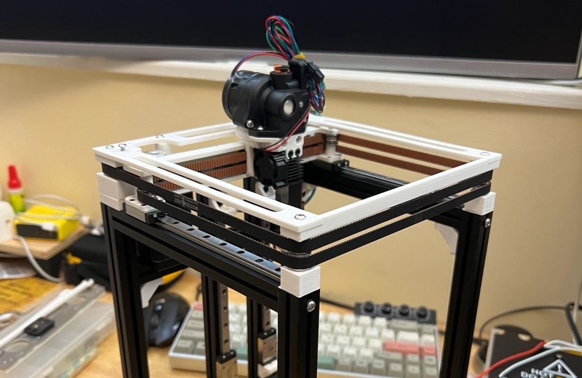
View of the assembled toolhead with the prototype hotend
Updated ABS hotend design
I cut slots out of the test parts to save on material
The belt retention mechanism worked very well, despite the tight fit.
Functional Prototype
This was the first functional prototype. While it would have benefitted from properly-machined parts, it proved the concept was viable.
V3: Key Takeaways
Belt Routing
Routing the belts around the front causes two main issues:
The front of the frame needs to be reinforced significantly to prevent the belts from pulling the frame out of square. This can be overcome with support plates, but those block access to the bed when starting a print and overall limit visibility and access.
Routing the belts in this manner causes the belt teeth to come into contact with the bearings more frequently. If I re-route the belts as I did in the original design, there’s only one point of unnecessary contact between the belt teeth and a bearing surface. Avoiding teeth-bearing interactions should reduce artifacts in the final print.
Re-routing the belts will allow me to stiffen the frame, have better access in the front, and provide more room for cooling. It may result in a slight size increase, but the benefits outweigh the costs. Using quality 5mm bearings will help with this.
Toolhead Design
The hotend should be sideways for the following reasons:
Less hot air blasted at 3D-printed parts
Clearer path for air to escape heatsink
Simpler mounting design
Moves nozzle forward for better rear motion clearance
Material Selection
Chromoly is ~3x stiffer than aluminum of the same thickness. Same with galvanized steel. Both can be ordered pre-bent from sendcutsend. This is a good material to explore using for the gantry, as it would likely save weight.
Future Designs (V4)
The v4 prototype design is in progress. It switches to the previous belt routing direction, improves ease of assembly, standardizes bolt lengths, and uses a refined belt tensioning mechanism, as well as returning to the use of sheet metal for the lower part of the gantry “sandwich” rather than aluminum extrusions. The majority of the rest of the frame can be re-used.